3. Zoetrope
Introduction
In this project, we aim to create a device called a Zootropio, capable of giving the illusion of movement through a sequence of images. To make the project more engaging, we will use a motor, a switch to control the direction, another switch to turn it on and off, and a potentiometer for speed control.
To enable the carousel to rotate in one direction only, we will introduce H-Bridges.
Bridge H
H-Bridges are known as integrated circuits (ICs). Integrated circuits are components that contain complex circuits within a very small space. You can access the integrated circuit through the pins that extend from the sides.
Necessary components
- H-Bridge
- 10 kilo-ohm resistor
- Motor
- Push button
- 9V battery
- Potentiometer
- Battery holder
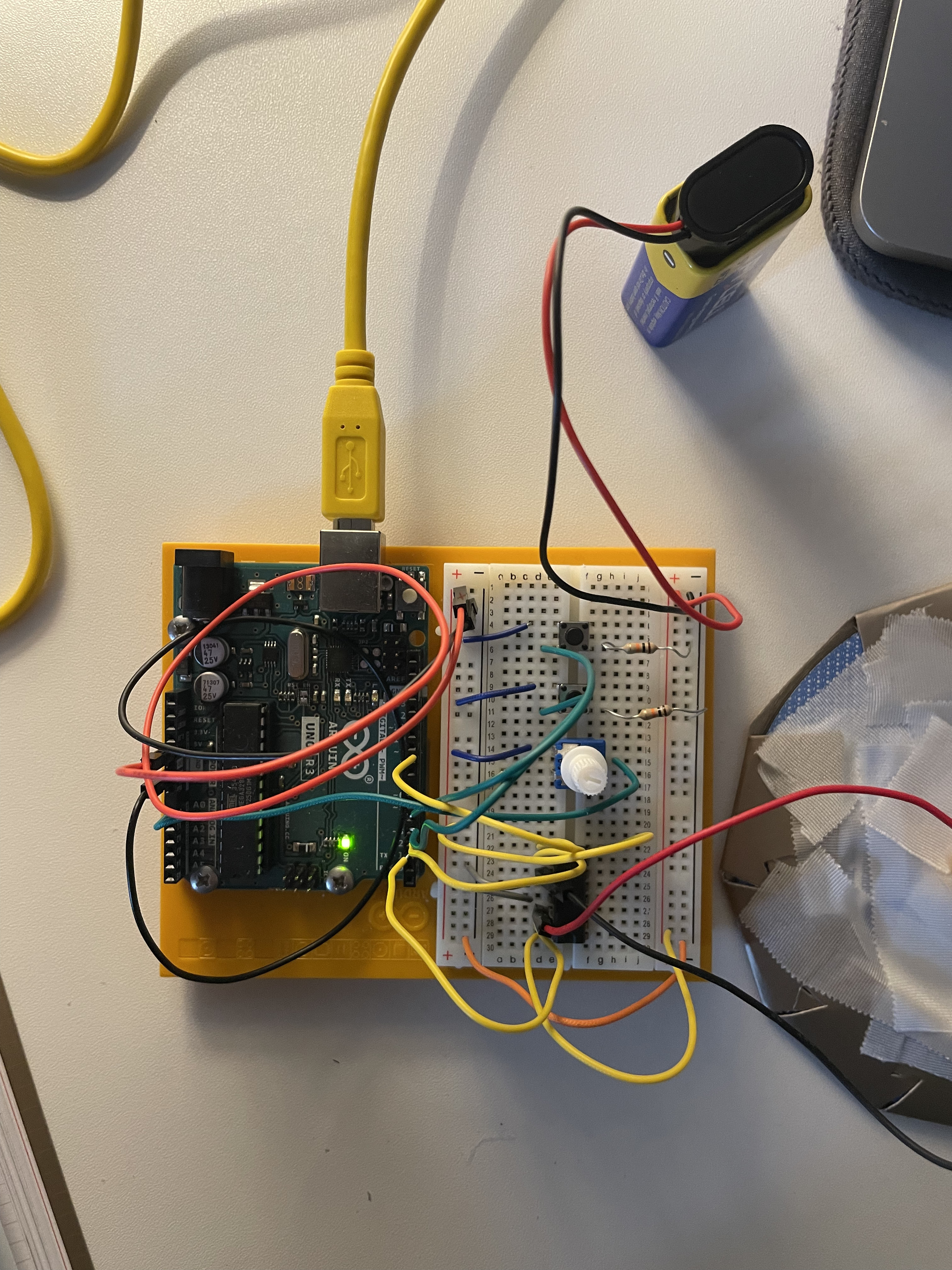
Construction
- Connect the power and ground to one side of the breadboard.
- Add 2 push buttons to the breadboard, connecting each one to a 10 kilo-ohm resistor with the other end of the resistor connected to ground. The button on pin 4 controls the direction, while the other button turns the motor on and off.
- Connect the potentiometer to the breadboard. Connect 5 volts to one side and ground to the other side. Finally, connect the center pin to Arduino's analog input 0.
- Place the H-Bridge on the breadboard. Connect pin 1 of the H-Bridge to Arduino's digital pin 9. This pin controls the motor; applying 5 volts turns it on, while 0 volts turns it off, enabling pulse-width modulation for speed control.
- Connect pin 2 of the H-Bridge to Arduino's digital pin 3, and pin 7 to digital pin 2. These pins communicate with the H-Bridge to specify the direction of rotation.
- The H-Bridge is powered from pin 16; connect it to 5 volts, and pins 4 and 5 should be connected to ground.
- Connect the motor to pins 3 and 6 of the H-Bridge.
- Connect pin 8 of the H-Bridge to the positive terminal of the battery.
Code explanation
const int controlPin1 = 2;
const int controlPin2 = 3;
const int enablePin = 9;
const int directionSwitchPin = 4;
const int onOffSwitchStateSwitchPin = 5;
const int potPin = A0;

int onOffSwitchState = 0;
int previousOnOffSwitchState = 0;
int directionSwitchState = 0;
int previousDirectionSwitchState = 0;

int motorEnabled = 0;
int motorSpeed = 0;
int motorDirection = 1;

void setup() {

  pinMode(directionSwitchPin, INPUT);
  pinMode(onOffSwitchStateSwitchPin, INPUT);
  pinMode(controlPin1, OUTPUT);
  pinMode(controlPin2, OUTPUT);
  pinMode(enablePin, OUTPUT);
  digitalWrite(enablePin, LOW);

}

void loop() {

  onOffSwitchState = digitalRead(onOffSwitchStateSwitchPin);
  delay(1);
  directionSwitchState = digitalRead(directionSwitchPin);
  motorSpeed = analogRead(potPin)/4;

  if(onOffSwitchState != previousOnOffSwitchState){
    if(onOffSwitchState == HIGH){
      motorEnabled = !motorEnabled;
    }
  }

  if(directionSwitchState != previousDirectionSwitchState){
    if(directionSwitchState == HIGH){
      motorDirection = !motorDirection;
    }
  }

  if(motorDirection == 1){
    digitalWrite(controlPin1, HIGH);
    digitalWrite(controlPin2, LOW);
  }else{
    digitalWrite(controlPin1, LOW);
    digitalWrite(controlPin2, HIGH);
  }

  if(motorEnabled == 1){
    analogWrite(enablePin, motorSpeed);
  }else{
    analogWrite(enablePin, 0);
  }

  previousDirectionSwitchState = directionSwitchState;
  previousOnOffSwitchState = onOffSwitchState;

}
Declared Variables:
-
controlPin1,controlPin2,enablePin: These variables define the control pins of the H-Bridge and the enable pin (for PWM control of the motor speed). -
directionSwitchPin,onOffSwitchStateSwitchPin: These variables define the pins to which switches are connected to control the motor direction and motor on/off functionality. -
potPin: This variable defines the pin to which the potentiometer is connected to adjust the motor speed. -
Other variables like
onOffSwitchState,previousOnOffSwitchState,directionSwitchState,previousDirectionSwitchState,motorEnabled,motorSpeed,motorDirectionare used to store switch states and control motor behavior.
setup() Function:
-
pinMode(): Configures the pins as either inputs or outputs required for H-Bridge and switch operation. The control pins (controlPin1,controlPin2,enablePin) are set as outputs to control the H-Bridge. The switches (directionSwitchPin,onOffSwitchStateSwitchPin) are set as inputs to read switch states. -
digitalWrite(enablePin, LOW): Initially sets the enable pin (enablePin) to LOW to disable the motor at startup.
loop() Function:
-
Reads the state of switches and potentiometer on each iteration of the loop.
-
digitalRead(): Reads the state of switches (onOffSwitchStateSwitchPin,directionSwitchPin) and saves the current state into variables (onOffSwitchState,directionSwitchState). -
analogRead(potPin): Reads the analog value from the potentiometer (potPin) and converts it to a value ranging from 0 to 1023. This value is then used to set themotorSpeedvariable controlling the motor speed. -
Handles switch state changes:
- If the on/off switch (
onOffSwitchStateSwitchPin) is pressed, toggles themotorEnabledstate (turns the motor on/off). - If the direction switch (
directionSwitchPin) is pressed, toggles themotorDirectionstate (changes the motor direction).
- If the on/off switch (
-
Controls the motor direction based on the
motorDirectionstate. IfmotorDirectionis equal to 1, the motor spins forward; otherwise, it spins backward. -
Controls motor activation and speed:
- If
motorEnabledis equal to 1 (motor is on), usesanalogWrite(enablePin, motorSpeed)to activate the motor at the current speed (motorSpeed). - If
motorEnabledis equal to 0 (motor is off), setsanalogWrite(enablePin, 0)to turn off the motor.
- If
-
Updates the previous switch values for the next cycle (
previousOnOffSwitchState,previousDirectionSwitchState).
In summary, this code allows control of a motor using Arduino, enabling the user to adjust motor direction and speed using switches and a potentiometer.