2. Motorized Pinwheel
Introduction
This project aims to simply rotate a colorful pinwheel using a motor! However, moving things requires a lot of energy, more than what Arduino can provide, and motors also require higher voltage.
Transistor
Transistors allow controlling high loads of current and voltage through the low output current of Arduino's pin, acting as a digital switch. When power is supplied to one of the transistor's pins, called the gate, it closes the circuit between the other two pins, called the source and drain. This way, a high-voltage motor can be turned on and off with Arduino.
Motors
Motors are inductive devices. Induction is a process whereby a varying electric current flowing through a wire is capable of creating a varying magnetic field. When electricity is supplied to a motor, a coil of copper wire tightly wound inside the motor creates a magnetic field, causing the motor shaft to rotate.
Necessary components
- 10 kilo ohm resistor
- 1N4007 diode
- Motor
- Button
- MOSFET
- Battery connector
- Battery
- Motor
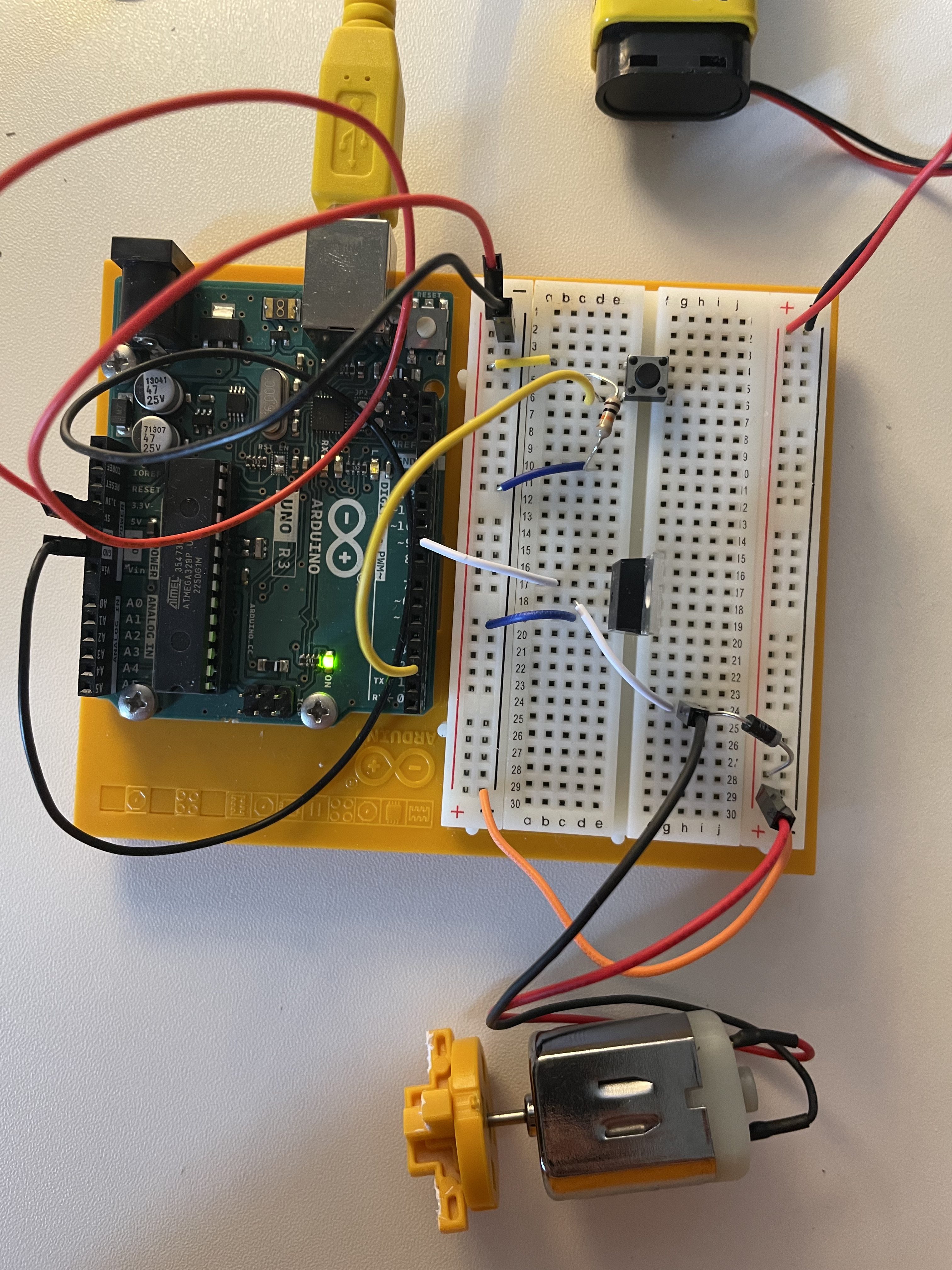
Construction
- Connect the power and ground of the board to the breadboard.
- Add a button to the board by connecting one side to power and the other to digital pin 2 of Arduino. Add a 10 kilo ohm resistor to ground on the output pin of the switch.
- Connect the 9-volt battery connector to the breadboard. When using circuits with different voltages, the grounds must be connected to create a single ground, so connect the battery ground to Arduino ground with a jumper wire. Finally, attach one end of the motor to the central pin of the connector to the 9-volt power supply.
- Place the transistor on the breadboard. Connect digital pin 9 to the left pin of the transistor. This pin is called the gate, and a voltage on the gate creates a connection with the other two pins. Connect one end of the motor to the central pin of the transistor, which is called the drain.
- Connect the motor power supply to the motor and the breadboard, then add the diode. It is a polarized component and should be inserted into the circuit in a single direction. The diode has a positive pole (anode) and a negative pole (cathode). Connect the anode to ground and the cathode to the motor power supply. This component is crucial as it helps prevent any back electromotive force generated by the motor.
Code explanation
const int switchPin = 2;
const int motorPin = 9;
int switchState = 0;

void setup() {
  pinMode(motorPin, OUTPUT);
  pinMode(switchPin, INPUT);
}

void loop() {
  switchState = digitalRead(switchPin);

  if(switchState == HIGH){
    digitalWrite(motorPin, HIGH);
  }else{
        digitalWrite(motorPin, LOW);
  }
}
Key Components:
- Variables:
switchPin: Defines the pin number connected to the switch.motorPin: Defines the pin number connected to the motor.switchState: Stores the current state of the switch (HIGH or LOW).
- Setup Function:
pinMode(motorPin, OUTPUT): Configures the motor pin as an output pin.pinMode(switchPin, INPUT): Configures the switch pin as an input pin.
- Loop Function:
- Reads the digital state of the switch using
digitalRead(switchPin)and stores it inswitchState. - Uses an
ifstatement to check the state of the switch:- If
switchStateisHIGH, turns on the motor by settingmotorPintoHIGH. - If
switchStateisLOW, turns off the motor by settingmotorPintoLOW.
- If
- Reads the digital state of the switch using
Overall, the code demonstrates a simple switch control for a motor using Arduino.