1. Keyboard Instrumental
Introduction
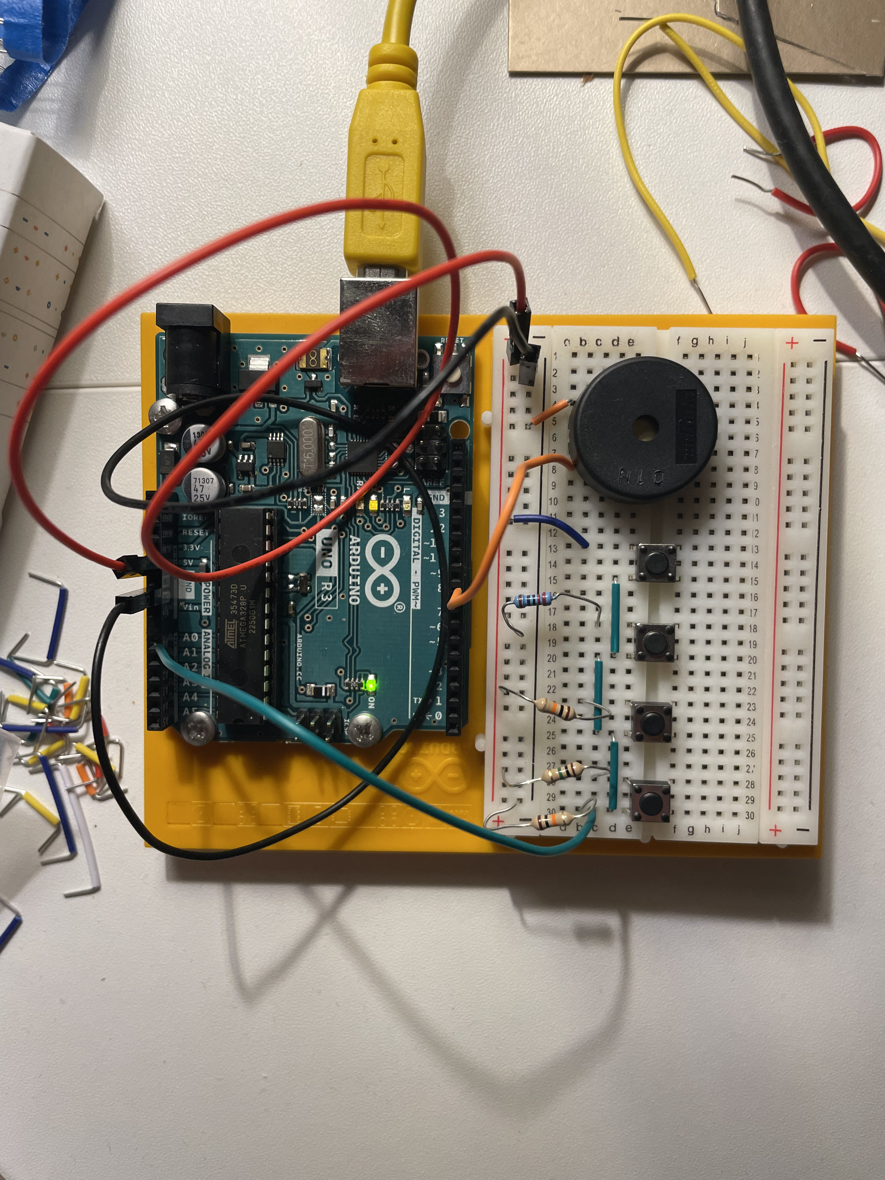
This project involves creating a simple musical keyboard using Arduino, pushbuttons, and a resistor ladder network. The resistor ladder network allows you to connect multiple pushbuttons to a single analog input pin on the Arduino. When a pushbutton is pressed, it completes a circuit and sends a different voltage level to the Arduino, which can then be interpreted to identify the pressed button and generate the corresponding musical note.
Necessary Components
- Arduino Uno: The microcontroller board that will process the sensor data and generate the sounds.
- Pushbuttons (4): These will be used as the keys of the musical keyboard.
- Resistors (4): Different resistors will be used to create the resistor ladder network.
- Piezo buzzer: This will be used to generate the musical tones.
- Jumper wires: These will be used to connect the components on the breadboard.
- Breadboard: This will provide a platform for prototyping the circuit.
Construction
-
Connect the Breadboard to Power and Ground:
- Insert the red power rail (usually labeled "+") from the Arduino power supply into the top red rail of the breadboard.
- Insert the black ground rail (usually labeled "-") from the Arduino power supply into the bottom blue rail of the breadboard.
-
Connect the Piezo Buzzer:
- Insert one leg of the piezo buzzer into the ground rail (blue) on the breadboard.
- Insert the other leg of the piezo buzzer into analog pin 8 on the Arduino.
-
Connect the Pushbuttons and Resistor Ladder Network:
- Place the four pushbuttons on the breadboard in a row, representing the keys of the keyboard.
- Connect one end of each pushbutton to a common ground point on the breadboard (usually the bottom blue rail).
- Connect the other end of each pushbutton to a different resistor. Use resistors with different values, such as 100 ohms, 220 ohms, 470 ohms, and 1k ohm.
- Connect the remaining ends of the resistors to analog pin A0 on the Arduino. This creates the resistor ladder network.
Explanation of the Resistor Ladder Network
The resistor ladder network is a circuit that allows you to connect multiple sensors or inputs to a single analog input pin on the Arduino. Each resistor in the ladder network creates a different voltage divider, resulting in different voltage levels at the analog pin when different buttons are pressed. The Arduino can then read these voltage levels and determine which button was pressed.
Code explanation
The provided code is written in C++ for an Arduino project. It utilizes analog input to control the generation of different musical tones.
int notes[] = {262, 294, 330, 349};

void setup() {
  Serial.begin(9600);
}

void loop() {
  int keyVal = analogRead(A0);

  if(keyVal == 1023){
    tone(8, notes[0]);
  }else if(keyVal >= 990 && keyVal <= 1010){
        tone(8, notes[1]);
  }else if(keyVal >= 500 && keyVal <= 990){
        tone(8, notes[2]);
  }else if(keyVal >= 5 && keyVal <= 10){
        tone(8, notes[3]);
  }else{
    noTone(8);
  }
}
Key Components:
- Variables:
notesarray stores frequency values (Hz) for different tones.keyValholds the analog input value from pin A0.
- Setup Function:
Serial.begin(9600)initializes serial communication for debugging.
- Loop Function:
- Reads the analog value from pin A0 (
keyVal). - Uses
ifstatements to checkkeyValranges and generate corresponding tones:- If
keyVal == 1023, plays the first note (notes[0]). - If
keyValis within specific ranges, plays corresponding notes from thenotesarray. - Otherwise, stops any ongoing sound (
noTone(8)).
- If
- Reads the analog value from pin A0 (
Overall, the code demonstrates how to map analog sensor input to control sound generation using Arduino.